NEED HELP?
WE ARE HERE TO HELP YOU
With the ever-increasing height of buildings, the requirements for reliable life safety systems becomes higher and higher. A key requirement in the life safety regulations is to ensure the safe escape and evacuation of people. Most fire related deaths are caused by the inhalation of smoke and toxic gases produced by the fire and not directly by the fire itself. Therefore, the most significant threat is the highly toxic smoke, which is a lethal cocktail made up of a complex mix of suspended particles and highly toxic gases.
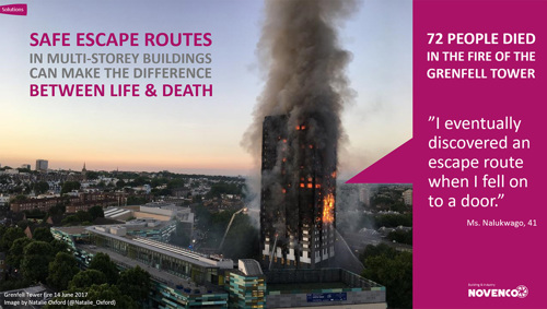
Although nowadays the buildings are more frequently equipped with sprinkler systems, this alone will not ensure the occupants are not exposed to toxic smoke in case of a fire. It is evident that sprinkler systems can contribute in life safety by controlling the fire within a compartment, but in many cases the sprinkler will not extinguish the fire. Therefore, an additional smoke control system with pressuration fan function is necessary to ensure that people can find a safe way out.
Smoke control systems form an element of the overall fire engineering strategy for apartment buildings and should be designed together with all the involved parties. It is the responsibility of the designer of the smoke control systems to ensure that any proposed systems compliment the fire engineering strategy and provide a suitable level of fire safety.
The main objective of these smoke control systems is to ensure safe evacuation of a building by keeping escape routes free from smoke. This can either be achieved by smoke extract systems or by pressure differential systems.
Air will naturally try to move from an area of higher pressure to an area of lower pressure. By increasing the pressure in the protected areas (i.e. the escape routes) above that in the areas where the fire is likely to occur (in this case the apartments) it is possible to prevent smoke spread into these escape routes.
The aim therefore is to establish a pressure gradient from the protected space to the unprotected space (fire room) while the doors are closed. In case of doors open, a suitable air velocity should be established over the door openings to prevent the spread of smoke into the protected space. This pressure gradient can be achieved through pressure differential systems with pressurisation fans.
For this purpose NOVENCO introduces the ClearChoice™ Pressure Differential Systems (PDS) as a solution for creating smoke free zones, that allow people to escape from buildings and tunnels and aid the firefighting services by preventing smoke spread through seams and cracks of physical barriers such as doors or other similar restricted openings.
The field of application differs for a variety of buildings and tunnels, where there is a need to protect means of escape such as stairwells, corridors, escape tunnels, lobbies, as well as for providing smoke free approach for the firefighting services.
To summarize, three major design objectives can be addressed:
This is the most important design objective of the pressurisation systems, where it is essential that tenable conditions for life safety are maintained in protected spaces for as long as they are likely to be in use by the building occupants.
Depending on the building classification, another design objective of the pressurisation systems is to protect firefighting access routes and keep them essentially free of smoke. In this case, the pressure differential system must be designed to prevent or at least limit the spread of smoke into the dedicated firefighting route under normal firefighting conditions.
The third objective of the pressurisation system can be to prevent the spread of smoke from entering sensitive spaces such as those containing items that are particularly sensitive to smoke damage.
In Europe, the requirements for smoke control systems are described in the European Standard EN 12101 “Smoke and heat control systems”. Specifications for pressure differential systems are described in EN 12101 part 6. Currently this part 6 with PDS kits is under revision and a part 13 will be added: “Pressure differential systems (PDS) - Design and calculation methods, installation, acceptance testing, routine testing and maintenance”.
Pressure differential systems are designed to maintain tenable conditions in protected spaces such as, escape routes, firefighting access routes, firefighting lift shafts, lobbies, staircases and other areas that require to be kept free of smoke.
These pressure differential systems create a differential pressure between the protected space and the unprotected space of the fire floor to prevent the smoke spreading from the unprotected space to the protected space.
In case of (simultaneous) open doors, the pressure differential system must be designed to create a minimum air velocity over the area of the open doors to prevent smoke from entering the protected space. To achieve this air velocity, the air supply fan to the protected space must supply sufficient airflow over the sum of the open-door areas.
An important factor for these pressure differential systems are the airflow paths throughout the building, not only where the fresh air supply is introduced, but also where that air (and smoke) will leave the building and what paths it will follow in the process.
For a typical pressure differential system three basic components are necessary:
To provide the best level of protection, the common escape route from each apartment door to the final exit door would be pressurised. Unfortunately, this is usually impractical due to the difficulties of providing and maintaining air release facilities from each apartment. It is therefore normal to provide air release from the common corridors/lobbies.
Pressure differential systems can be divided in two commonly used techniques:
In both variants, the pressure in the protected space is higher than the pressure in the unprotected space, where the set value of the pressure differential is of the essence. If the pressure differential is too low, smoke may ingress the protected space. Too much pressure when all doors are closed will make doors opening into the pressurised space difficult to open and will impede escape into the protected area. The objective of pressure differential system variants is the same; keep the protected space, such as a stairwell or escape tunnel, free of smoke.
In a pressurisation system, a pressurisation (supply) fan is used to pressurize the protected space.
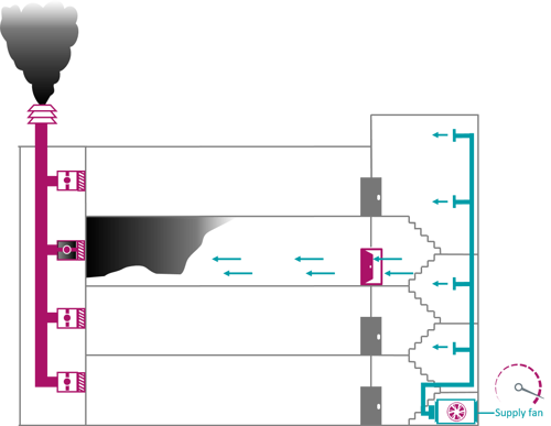
With the doors closed, the pressure in the protected space (for example a staircase) is set to the required pressure difference using a supply fan in combination with a control system. In case a door opens, the supply pressurisation fan will create an airflow over the door opening preventing smoke from entering the protected space. To ensure an effective system, an air release path with sufficient capacity must be available. This can for example be a smoke shaft with fire rated smoke control dampers.
Pressurisation systems can be designed with passive or active air release. For a passive air release (i.e. natural air release), the pressure drop of the complete air release path must be very low (< 30 Pa) to ensure the airflow over the open door, resulting in very large natural openings, shafts, fire rated smoke control dampers and roof cowls suitable for smoke control systems.
With an active air release (i.e. mechanical smoke extract), a variable speed smoke extract fan will ensure the airflow over the door opening, resulting in much smaller shafts and smoke control dampers.
In a depressurisation system, a smoke extract fan is used to depressurize the fire compartment and create a differential pressure with the protected space.
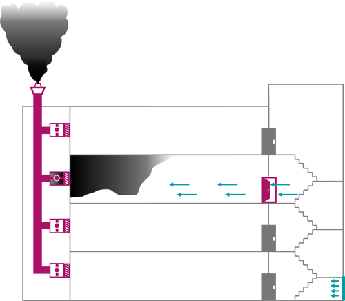
With the doors closed, the pressure differential between the protected space and the lobby is set to the required pressure difference using a smoke exhaust fan. If a door towards the protected space is opened, the system creates sufficient air velocity over the door opening.
Depressurization systems can be designed with passive or active air supply. In case of a passive air supply, the air supply opening (often an AOV) should be large enough for a very low pressure drop.
In the United Kingdom, under Approved Document B (ADB), the common spaces requiring smoke ventilation are the stairs and the lobbies and/or corridors opening onto the stairs. Powered smoke ventilation may be used as an alternative to natural smoke ventilation systems, as recommended in ADB. Benefits of powered systems include specified extraction rates, limited wind sensitivity issues, known capability to overcome system resistances and reduced shaft cross sections.
ClearChoice mechanical air extract systems are used for the ventilation of firefighting lobbies and escape routes. In the UK, this powered smoke ventilation system is considered an equivalent to the general recommendations of ADB and BS 9999. Further guidance is to be found in the BS9991 and the Smoke Control Association Guidance on Smoke Control to Common Escape Routes in Apartment Buildings.
The principle of the system is to provide mechanical extraction from each of the firefighting lobbies with natural fresh air being drawn in from the stairwell to clear the lobby of smoke ingress during the means of escape and firefighting periods. The extract (smoke) fan will run at the design duty when the supply source is available (door to stairwell is open) and will ramp down when the source is removed (door to stairwell is closed). This will be controlled by a differential pressure measurement within each of the lobbies.
An AOV (automatic opening ventilator) will be provided to the stairwell to provide the required makeup air. The extract shaft will be connected to the lobbies at each level by a fire rated smoke control damper. The system can be activated through a fire detection system or smoke detectors.
This system is also installed in the latest Berkeley Homes investment, a luxurious development at the Royal Arsenal riverside in South East London, NOVENCO Building & Industry has been contracted to design and supply solutions for, among others, ventilation and temperature control of the corridors and stairs and efficient smoke clearance of public areas.
Within the current EN 12101 part 6 there are 6 classifications for pressure differential systems based on the use of the building. For very small buildings, class A from the EN 12101-6 can be used and for more complex buildings (hotels, hospitals, nursing homes) a selection can be made from the other system classifications.
Within the EN 12101 part 6, the classes A, C, D and E are exclusively intended as support for safe escape. For classes B and F, in addition to safe escape, also a smoke free firefighting access is considered.
| System class | Examples of use |
|---|---|
| A | No evacuation unless directly threatened by fire. Unlikely that more than one door to the protected area will be open at the same time. |
| B | Firefighting support. The fire brigade may be exposed to a developed fire which needs to be approached with a low smoke level. |
| C | Immediate, simultaneous, short-term evacuation in the event of fire. Persons are expected to be alert, aware and familiar with their surroundings. |
| D | Immediate, simultaneous, long-term evacuation in the event of fire. Persons are less alert (sleep) or not familiar with their surroundings (hotel). |
| E | Phased, long-term evacuation in case of fire. First fire floor, then other floors. Possibility of high fire load. |
| F | Firefighting support. The fire brigade may be exposed to a developed fire which needs to be approached with low smoke levels. |
The design conditions assume that a building will not be evacuated unless directly threatened by fire. The level of fire compartmentation shall be such that it is usually safe for the occupants to stay in the building. (Stay put strategy) Therefore, it is unlikely that more than one escape door to the protected area will be open at the same time.
System class A may not be used for a building with multiple building functions.
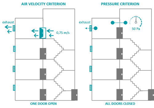
| Class A systems for safe escape. Defend in place. | |
|---|---|
| User : | No conditions are imposed on the user. |
| Evacuation : | No evacuation or only partial evacuation. |
| Possible building function : | Residential building. Not for multipurpose buildings. |
| Speed over open door : | 0,75 m/s |
| Exit door : | Closed |
| Number of doors simultaneously : | 1 |
| Pressure criterion : | 50 Pa (all doors closed) |
| Details : | Simple system. No evacuation or direct fire hazard. It is safe for users to stay in the building. |
The design conditions for Class C pressurisation systems are based on the assumption that the users of the building are all evacuated at the same time when the fire alarm signal sounds.
Simultaneous evacuation is assumed during the early stages of fire development.
Some smoke leakage can be tolerated, but this smoke must be exhausted by the airflow of the pressure differential system.
Persons to be evacuated are presumed to be alert, aware and familiar with their environment, minimising the time required for evacuation.
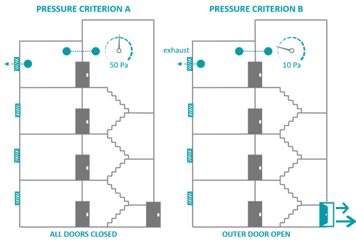
| Class C systems for safe escape with simultaneous evacuation. | |
|---|---|
| User : | Users are alert, aware and familiar with their environment. |
| Evacuation : | Simultaneous evacuation in a short time. |
| Possible building function : | Office buildings. |
| Speed over open door : | 0,75 m/s |
| Exit door : | Closed at pressure criterion 1, open at pressure criterion 2 |
| Number of doors simultaneously : | 1 |
| Pressure criterion 1 : | 50 Pa (all doors closed) |
| Pressure criterion 2 : | 10 Pa (only exit door open) |
| Details : | Short evacuation, some smoke allowed. |
System class D pressurisation systems are for buildings where users can sleep, e.g. hotels, hostels and institutional buildings. The time it takes for users to get to a protected space before they reach the exit, may be longer than in a familiar environment.
The users may be unfamiliar with the building or may need help to get to the last exit or protected space. Class D pressurisation systems are also suitable when the presence of a pressure differential system also serves as an equivalence for a second escape route.
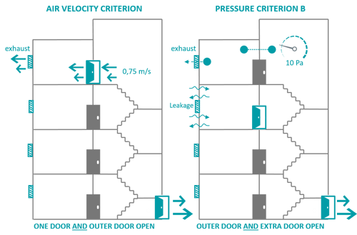
| Class D systems for safe escape with sleep risk. | |
|---|---|
| User : | Building in which users can sleep. Users are less alert and may not be familiar with their surroundings. |
| Evacuation : | Simultaneous evacuation over a longer period of time. |
| Possible building function : | Hotels, residential buildings, health care. |
| Speed over open door : | 0,75 m/s |
| Exit door : | Open |
| Number of doors simultaneously : | 2 |
| Pressure criterion 1 : | 50 Pa (all doors closed) |
| Pressure criterion 2 : | 10 Pa (only exit door open) |
| Details : | Long term evacuation. Can also be used if only one escape route is available, while two are needed. |
At the basis of design should be a fire safety report approved by the authorities having jurisdiction, which stipulates the building function and classification, fire safety design and evacuation concept, including safety targets.
Since pressure differential systems can have a big impact on the building structure, such as structural shafts, it is strongly advised to incorporate the pressure differential system design at an early stage of the design.
For the design of a pressure differential system, some key parameters shall be set:
Minimum pressure difference
In the current EN 12101 part 6, the minimum pressure difference is set at 50 Pa. However, in combination with larger doors (> 2 m²) and door closers, this may be an unfeasible requirement in combination with the maximum door opening force of 100N (see related section).
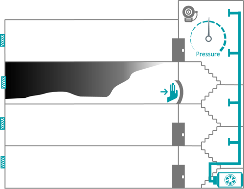
In the upcoming EN 12101 part 13, this minimum pressure has therefore been reduced to 30 Pa, which is proven to be more than sufficient for an effective pressure differential system.
Minimum air velocity
When the doors between the protected and unprotected spaces are open, the pressure differential criterion is replaced by the airflow criteria based on a minimum air velocity over the door opening. Since the air/smoke release path is open on the fire floor only, this airflow velocity requirement only needs to be met on that fire floor.
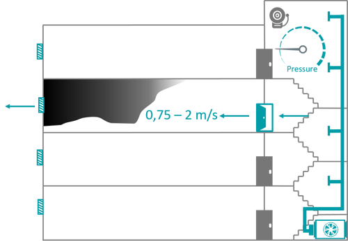
Depending on the classification of the air pressuration system, this requirement must also be met when the final exit door is open. In such a case, the pressure differential system must be designed to still meet the minimum velocity requirement over the door opening between the protected and unprotected space.
Maximum door opening force
The maximum door opening force is closely related to the pressure differential over the closed door, in combination with the door size and eventual automatic door closers.
As a standard in the EN 12101 part 6, the opening force at the door handle may not exceed 100 N. This requirement must be met on all floors including the fire floor and for each door within the escape routes when the pressure differential system is in operation.
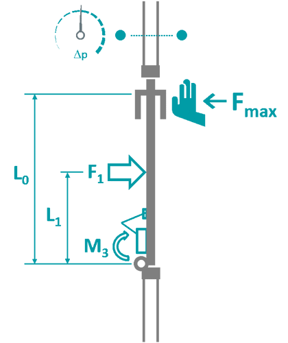
The force required (Fmax) to open the escape doors may not exceed 100 N.
Influential factors:

Maximum response delay
To ensure a smoke-free protected space, a pressure differential system must be activated with quick response fire alarm systems, such as smoke detectors. Pressure differential systems must be initiated within 1 minute of activation (fire alarm signal), by which time all the necessary components shall be in the correct operating position (e.g. dampers, vents) and the fan(s) shall have started. The full air pressurisation system should be fully operational within 2 minutes after activation. As an indication, the response delay time is the time for the PDS to achieve either the pressure differential objective (door closed, max. opening force) or the air velocity over the door opening objective (door open).
For pressure differential systems, the air intake must be directly from the outside in such a way that it is not contaminated by smoke from a fire within the building. Preferably, the air intake shall be on ground level. If this is not possible, at least 2 independent inlets can be positioned at roof level or elsewhere in the facade under certain specific requirements. In such a case, each inlet shall be independently capable of providing the full air requirements of the pressure differential system. The intake ducts must both be fitted with a smoke detector and shut-off damper, in order to shut off that duct with a damper in the event of smoke detection.
The air supply to staircases shall be distributed evenly over the height of the staircase. A vertical shaft with an air supply point (minimum) every 3 levels will normally provide this performance.
When the pressure differential system is running, air will flow from the protected space into the unprotected space. This air release path may be passive, for example, from windows or a natural smoke shaft or active by fan control. Passive air release can be influenced by wind and thermal effects (stack/chimney effect), which must be taken into consideration.
Differential pressure control can be achieved by:
In the event of a fire in a building, the smoke behaviour and airflow patterns are influenced by a number of important factors:
Buoyancy due to the expansion of hot gases from the fire
With a fire hot smoke is produced, from which buoyancy forces are experienced due to the reduced density of the smoke. Because of the reduced density, the smoke wants to move up. If leakage paths between storeys exist in a building, this can result in the smoke spreading to other storeys. Furthermore, due to the expansion of the smoke volume, smoke can also spread through leakage paths through vertical barriers, such as doors, partitions and even walls. Because of the pressure difference between the (hot) ceiling and (relative colder) floor, typically smoke leaks through gaps at the top of the door, where cool air is drawn into the fire zone through gaps in the bottom.
Thermal expansion of hot smoke
Because of the expansion of gases at high temperatures, typically a build-up of pressure is induced causing the smoke to flow out of the fire compartment.
Meteorological influences
Also, meteorological influences have to be taken into consideration for pressure differential systems. Take for example, temperature differences (summer/winter) or wind pressure on the facade of a building. Temperature differences can lead to differences in density, which in turn leads to the so-called chimney effect.
What we tend to forget is the dynamics of the outside air pressure. The average atmospheric pressure is 1,013 hPa (= 101,300 Pa). A pressure differential installation is generally controlled at a pressure difference between 30 and 50 Pa, which is only a fraction of the outside air pressure.
Stack effect (chimney effect)
Differences in the outside and inside temperature lead to differences in density. For example, in the wintertime the air in the building is heated. This warmer air rises, creating a flow of air upwards. Leakage through gaps, (open) windows and doors, among other things, will cause the (heavier) cool indoor air to pass through the building from bottom to top. During the summer, exactly the opposite happens when the air inside the building will be colder than the outside ambient air. This phenomenon is also described as the ‘reverse’ stack effect because the flow of air is downward.
In both cases, there will be a neutral pressure plane at some intermediate point in the vertical shaft or building. At this neutral pressure plane the internal air pressure is equal to the external air.
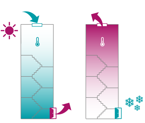
For the Burj Khalifa in Dubai for example in the summertime where the outside temperature is 46°C and the inside temperature is 21°C, assuming that the external air pressure and barometric pressure are constant over the height of the building, the pressure difference due to the stack effect is expressed as:

Where:
| Δp | pressure difference (Pa) |
| Cs | stack effect coefficient 0.0342 (K/m) |
| a | atmospheric pressure (Pa) |
| h | height above neutral plane (m) |
| T0 | absolute outside temperature (K) |
| T1 | absolute inside temperature (K) |
For an assumed shaft height of 700m and an atmospheric pressure of 1.012 hPa, the resulting pressure differential with the neutral plane at the top and bottom of the shaft will be +320 Pa and -320 Pa respectively.
But even for a lower building with a staircase of 60 meters, this stack effect can have a large influence. With an outside temperature in the wintertime of -10°C and an inside temperature of 20°C, the resulting pressure differential will be -40 Pa and +40 Pa at the respective top and bottom of the staircase. For pressure differential systems, where the system is regulated at pressure differentials around 30 Pa, it is clear that this stack effect needs to be taken into consideration!
Since a building is never 100% airtight, this effect will always occur, especially noticeable in high-rise buildings. This can create large differences between the pressure at the bottom and at the top of the stairwell or elevator shaft.
For higher buildings, a stable reference pressure is therefore often indispensable for proper control of a pressure differential system.
Wind pressure influences
Due to wind, pressure zones around the building will vary. On the side of the building on which the wind blows, the wind speed is reduced causing a build-up of pressure. As the wind is deflected and accelerated around the building, on the other side there will be a reduction in pressure. As the building is leaky, for example with open windows and doors, there will be air movement through the building, which can have an influence on pressure differential systems.
It must be noted that it is very difficult to predict the wind forces accurately and therefore also the resulting airflows within the building.
Other ventilation systems
Also, other ventilation systems can have an influence. These systems can supply combustion air to the fire zone, transport smoke or create pressure differentials in a building. Normally these systems are shut down in the event of a fire.
All above influence factors have to be taken into consideration when designing an air pressursation system. Especially pressure differences throughout the protected space, caused by for example the stack effect or wind, can have a negative influence on the PDS:
Pressure differential systems can be implemented in different ways:
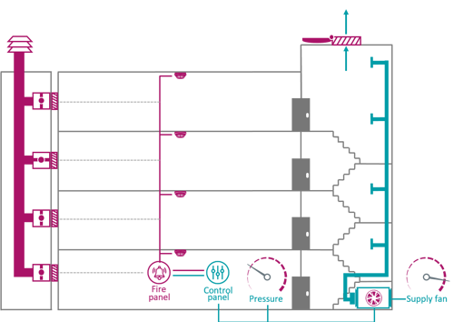
With a passive pressure differential system, no pressure sensors or fan speed controllers (such as frequency inverters) are used. Air is continuously supplied to the protected area by means of a pressurisation fan. A mechanical barometric pressure relief damper takes care of the pressure differential control. In the fire compartment, a minimum of two independent facade openings or a natural smoke exhaust shaft must be available as air release. If the door from the protected area to the fire compartment opens, the pressure relief damper will automatically close and the air will flow over the open door towards the air release vents.
The barometric relief damper is normally positioned on the top of the protected space, for example a staircase. The opening pressure difference to the outside is set at the time of commissioning.
As there are no pressure sensors in a passive system, the air release vents must be completely natural. To prevent the barometric damper from opening whilst a door is open, the pressure drop of the air release path must be well below the opening pressure (30-50 Pa) of the relief damper. This results in very large air release vents, such as a smoke extract shaft or facade openings.

With an active pressure differential system, the system is controlled by pressure sensors. These differential pressure sensors register the pressure difference between the protected space and the adjoining rooms or fire compartment. On the basis of this information, the pressure difference in the protected space in relation to the adjoining room is controlled by a speed-controlled fan. This is done by means of variable speed drives (VSD), such as frequency inverters.
In case the door to the fire compartment opens, the pressure sensors will register this pressure drop. The fast response control system will speed up the fan(s), which results in the required air velocity over the open door(s) towards the air release openings or exhaust shaft.
For an active presurisation system, no (pressure relief) opening is necessary in the protected space. In case of a pressurisation system, a pressurisation fan supplies air to the protected space, such as a staircase. Pressure differential sensors between the protected and unprotected space register the differential pressure, on the basis of which the supply fan is regulated. If a door towards the unprotected space opens, the differential pressure sensors will register this and increase the fan speed until the required airflow for the velocity over the open door is reached.
In an active system, both natural and mechanical air release shafts can be applied. In case of a natural exhaust shaft, the pressure drop of the air release path must be kept well below the (30-50) Pa pressure difference to ensure the air velocity over the open door. This will require very large exhaust shafts or (multiple wind independent) facade openings.
In a mechanical air release shaft, the airflow and pressure drop of the air release path is regulated by a speed-controlled smoke exhaust fan. As a result, the smoke exhaust shaft can be dimensioned at a fraction of a natural exhaust shaft.
| PASSIVE PRESSURE DIFFERENTIAL SYSTEMS | ACTIVE PRESSURE DIFFERENTIAL SYSTEMS |
|---|---|
| Regulated with barometric pressure relief dampers (no pressure sensors necessary). | Regulated with variable speed fans (pressure sensors necessary). |
| Only natural air release vents possible. | Both natural and mechanical air release vents. |
| Low resistance and thus large natural air release openings or shafts. | Small mechanical air release exhaust shafts (shaft area up to 75% smaller!). |
| No mechanical extract, larger leakage losses at supply. | With mechanical air extract, only small leakage losses at supply. |
| Only suitable for low buildings (up to 60m). | Suitable for all types of buildings (modular). |
| No fail-safe control of pressure relief dampers. | Fail-safe control with backup pressure sensors. |
| Pressure regulation only possible at pressure relief damper (fixed position). | Pressure regulation with accurate differential pressure sensors at any position. |
| Higher failure risk due to meteorological influences, summer, winter, wind. Pressure setting based on conditions at commissioning. | Meteorological influences, such as stack effect and wind pressure can easily be controlled with real-time measurements at any level. |
| Pressure relief setting at commissioning depending on weather conditions. | Differential pressure setting independent of weather conditions. |
| Pressure relief opening to outside necessary in protected space. | No pressure relief opening to outside necessary in protected space. |
Below is a comparison of both types of differential pressure systems for an example 16 storey building. The assumed door size is 0.85m x 2.3m with a leakage area of 0.2m² per floor. For the natural air release shafts, a maximum air velocity of 2 m/s was assumed to determine the required shaft areas. For the mechanical exhaust shaft, an air velocity of 8 m/s was considered.
|
System principle |
Active PDS |
Passive PDS |
|||||||
|
System |
Supply |
Exhaust |
Supply |
Exhaust |
|||||
|
Airflow |
Shaft |
Airflow |
Shaft |
Airflow |
Shaft |
Shaft |
Vents |
||
|
Class A |
6.000 |
0,21 |
6.000 |
0,21 |
10.000 |
0,35 |
0,80 |
2x 0,60 |
|
|
Class B |
34.000 |
1,20 |
14.000 |
0,48 |
50.000 |
1,74 |
2,00 |
2x 1,50 |
|
|
Class C |
6.000 |
0,21 |
6.000 |
0,21 |
21.000 |
0,73 |
0,80 |
2x 0,60 |
|
|
Class D |
12.000 |
0,42 |
6.000 |
0,21 |
26.000 |
0,90 |
0,80 |
2x 0,60 |
|
|
Class E |
13.000 |
0,45 |
6.000 |
0,21 |
27.000 |
0,94 |
0,80 |
2x 0,60 |
|
|
Class F |
34.000 |
1,20 |
14.000 |
0,48 |
50.000 |
1,74 |
2,00 |
2x 1,50 |
|
|
Average active |
0,59 |
0,29 |
Passive |
1,04 |
1,14 |
1,71 |
|||
Summarized from this example, for an active system with mechanical supply and exhaust versus a passive system with mechanical supply and natural exhaust with a shaft:
Example class D system:
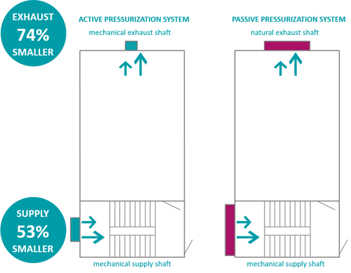
Notes:
This is only a sample calculation. No rights can be derived from it. The design depends on many factors and must be determined by an experienced fire safety engineer.
The ClearChoice systems are advanced smoke control systems from NOVENCO. With the ClearChoice Pressure Differential System (PDS), NOVENCO offers an active PDS with a lot of interesting features:
FULLY COMPLIANT SYSTEM
CLEARCHOICE COMPONENTS
CLEARCHOICE FAST RESPONSE CONTROL SYSTEM
SERVICE AND MAINTENANCE
As a pressurisation system supplier, NOVENCO offers not only delivery of products, but complete turn-key solutions. Our systems organisation is designed to handle complex projects, from design to delivery, installation, commissioning, hand-over, service and maintenance.
At the core of our developments is innovation in our products and solutions. With more than 70 years of experience, NOVENCO has been at the forefront of innovative ventilation solutions with a focus on efficiency and reliability. Our innovative products and solutions are characterized by high quality and reliability and our customers can count on tailored solutions that fit seamlessly with their specific requirements and wishes.
Every project has their own specific requirements and therefore require appropriate, tailored solutions. However, it is not the specifications that make the solution unique, but the specific project needs. Therefore, the standard modular solutions from NOVENCO are always tailored to the customer and project requirements and wishes. As a system supplier of smoke control systems, NOVENCO can dimension the systems using deterministic and probabilistic calculation methods. Furthermore, advanced simulation software is also used. When required, products are subjected to Factory Acceptance Tests (FAT), while the functioning of the entire system is assessed during extensive System Acceptance Tests (SAT).
Our systems group specializes in ventilation and smoke control systems for tunnels, car parks and buildings. As a system supplier we offer complete turn-key solutions for complex projects:
With a production area of approximately 30,000 m² in the factory in Denmark, all fans are developed and produced in-house. A fully equipped R&D department has access to one of the most advanced aerodynamic laboratories around the world.
As a certified smoke control company, NOVENCO is certified to design, deliver, install and commission complete smoke control systems.
In order to meet the obligations imposed by law on the availability of smoke control systems, service and maintenance are vital. Over a period of many decades, inspections and maintenance must be carried out in order to continue to meet the performance requirements and guarantee safety. NOVENCO has a dedicated service and maintenance department, which takes care of the maintenance of these important life safety systems.
For the pressure differential systems, NOVENCO offers a wide range of pressurisation fans and certified, variable speed (smoke) extract fans.
For the pressurisation fans, NOVENCO offers special axial fans with low inertia impellers and anti-stall operating areas for stable operation and high-speed operation in all conditions.
Since 2020, NOVENCO also offers their highly efficient ZerAx® range of axial flow fans as certified variable speed smoke fan packages in accordance with the EN 12101 part 3 (2015). These smoke fan packages are high temperature tested and certified in combination with a frequency converter and suitable for certified active pressure differential systems. In the event of a fire in the building, this allows variable speed-controlled smoke extract, whilst making sure that the differential pressure is kept within the specified range. The outcome is a highly reliable solution with maximum flexibility to control pressure differential systems in all possible operating conditions.
Please check the related products section below or contact us for more information on our design support, products and expertise for pressure differential systems.

NOVENCO Building & Industry
Oeverup Erhvervsvej 50-52
4700 Naestved
Denmark
Tel. +45 70 77 88 99
info@novenco-building.com
DK 16 92 66 47
Opening hours OFFICE
Monday - Thursday 8.00 AM to 4.00 PM CET
Friday 8.00 AM to 3.30 PM CET
Opening hours GOODS IN and OUT
Monday - Thursday 6.30 AM to 2.30 PM CET
Friday 6.30 AM to 2.00 PM CET
NEED HELP?